By popular request...
NOTE: When converting a G36 (or any other) pistol grip for use in a conversion, you MUST use the ENTIRE SL8 FCG.
When drilling the holes for the locking lever pin, most G36 lowers already have the spot marked (on both sides)... by-product of the plug used in the injection process I assume. Only 2-pos and 3-pos lowers need the hole drilled. 4-pos lowers already have the hole.
![Image]()
![Image]()
![Image]()
![Image]()
At this point the BHO should move upwards and spring back downwards. If it does not, check the location of the spring against the BHO lever... make sure it is on the RIGHT-SIDE.
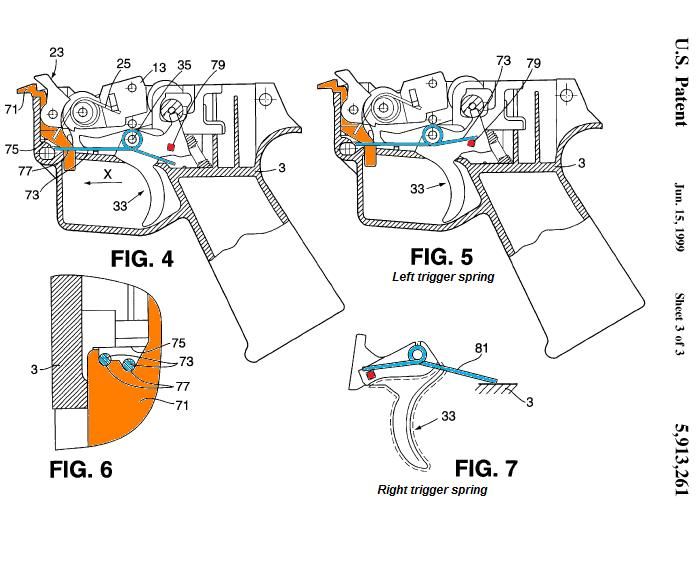
The trigger should also operate full-range freely and spring back into position. If not, double check spring placement.
![Image]()
![Image]()
![Image]()
Make sure the sear toggles freely. If you feel it bind or it does not toggle up/down, you may have missed the spring hole in the trigger and the sear spring is bound-up. Remove the sear and try again.
![Image]()
![Image]()
NOTICE: In the image below, the right side spring leg is in the wrong location. It is actually supposed to be tensioned against the polymer cross-wall at the bottom of the housing, not against the pin as shown.
![Image]()
At this point, the hammer should lock back properly and release with trigger pull. If not, double check spring placement AND sear-spring installation.
![Image]()
![Image]()
![Image]()
Locking-lever installation is the most time-consuming step for the first-timer. BE PATIENT as you will probably have to retry it a few times to get it right. Rushing this step will only get you more frustrated.
![Image]()
![Image]()
![Image]()
![Image]()
![Image]()
![Image]()
![Image]()
![Image]()
NOTE: When converting a G36 (or any other) pistol grip for use in a conversion, you MUST use the ENTIRE SL8 FCG.
When drilling the holes for the locking lever pin, most G36 lowers already have the spot marked (on both sides)... by-product of the plug used in the injection process I assume. Only 2-pos and 3-pos lowers need the hole drilled. 4-pos lowers already have the hole.


At this point the BHO should move upwards and spring back downwards. If it does not, check the location of the spring against the BHO lever... make sure it is on the RIGHT-SIDE.
The trigger should also operate full-range freely and spring back into position. If not, double check spring placement.


Make sure the sear toggles freely. If you feel it bind or it does not toggle up/down, you may have missed the spring hole in the trigger and the sear spring is bound-up. Remove the sear and try again.


NOTICE: In the image below, the right side spring leg is in the wrong location. It is actually supposed to be tensioned against the polymer cross-wall at the bottom of the housing, not against the pin as shown.

At this point, the hammer should lock back properly and release with trigger pull. If not, double check spring placement AND sear-spring installation.


Locking-lever installation is the most time-consuming step for the first-timer. BE PATIENT as you will probably have to retry it a few times to get it right. Rushing this step will only get you more frustrated.