
I just finished doing this for the FiveSeven so I figured I should be able to make it work for a USP. I bought a cheap USP parts kit from EveryGunPart, and I'm reverse engineering the parts to make CAD files. My cousin is supposed to loan me a USP45 to measure, but my kit is a USP40, so I'm hoping you guys can fill in the blanks. I've reverse engineered a p2000sk before, and from what I can tell there are a lot of similarities such as frame rails and trigger mechanism, the USP40 slide will even slide onto the P2000sk frame. The main thing I need is distance between the 4 pins (hammer, sear, trigger, slide stop), and some overall frame measurements like height, width, and length. Also, I know the 45 frame is bigger than the 9/40, but how much bigger? Hopefully I can get my hands on some other frames and post the measurement differences in this thread.
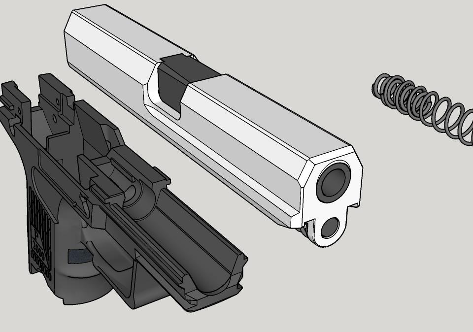
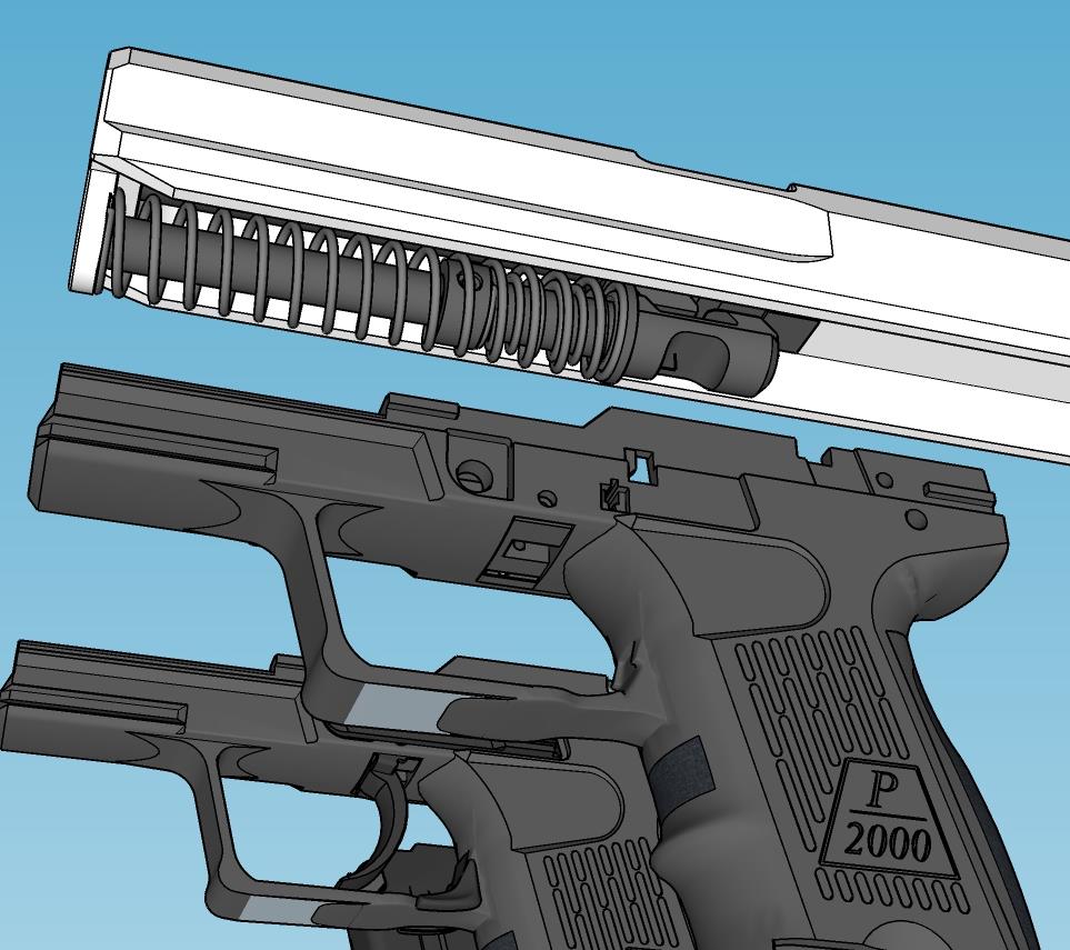
The way I normally do this is to fully reverse engineer the parts as is, then start modifying some things to be 3D printer friendly (beef up some thin parts, etc), so I'll have CAD files of both available when this project is finished. Also, the printed frame doesn't necessarily have to be a straight USP frame, I can remix it with some newer features like P2000 or P30 backstraps, so if you have any ideas for improvements let me know. Another thing I'm considering is building this kit as a 10mm, since the frame I have access to is the larger USP45 frame there should be room for the cartridge length, it's just a factor of finding a magazine that fits and tweaking the mag catch design/location.
Normally I sell these CAD models, but if I get some community support on this they'll be free for you guys.
If you guys don't mind taking some measurements for me, the best way to do it is to drift the pins out slightly and then measure with calipers outside-to-outside, then inside-to-inside edges of the pins, then measure the pin diameter. It's easier to infer the correct center-to-center measurement this way. If you do this from each pin to the 3 other pins, I can triangulate their positions on the frame.
A = hammer axle
B = sear pin
C = trigger pin
D = slide stop pin
So A to B/C/D, B to A/C/D, C to A/B/D, & D to A/B/C.